Showing posts with label PICAXE. Show all posts

Monday, May 2, 2022

Outdoor LED lighting controller

Introduction

This is a simple project which is a lighting controller for the inexpensive LED tape which is widely available from marketplace sites and is designed to be powered from 12V.

LED tape lights

The requirements for this project were:

  • Automatically turn the LEDs on at dusk and turn them off at dawn
  • Run the LEDs at a dim brightness during normal operation, or at high brightness when high brightness mode is enabled
  • Have a button for selecting high brightness mode. High brightness mode shall automatically be turned off after a time period
  • Have good efficiency

Preliminary testing

Prior to building the controller, the waterproof LED tape was installed as desired around the outside of my house. Around 8 metres of LED tape was installed in three separate lengths and mains flex was wired between each of the three runs and a central location where the controller will be installed along with its light sensor.

The LED tapes were all connected to a bench power supply in parallel for testing.

At the design voltage of 12V, the LEDs are at full brightness and consume around 2A of current for a total of 24W of power. The LEDs are quite bright at this power and the brightness is far too excessive to be used all night, not to mention the high operating costs over the long term.

The voltage was turned down until a sensible brightness for all-night operation was found. This was found to be in the range of 7.90V to 8.10V, with the current varying from 0.05A to 0.10A, and the power from 0.395W to 0.810W. With this in mind, a target voltage of 8.00V was chosen, which should result in a power consumption of only 0.6W (plus overheads from the mains power supply), resulting in low running costs.

Design

The power section of the design was be based around one of the inexpensive and widely available LM2576 buck converter boards. The board was modified to replace the trimmer potentiometer with fixed resistors to avoid future unreliability, and the Enable pin was carefully desoldered from the PCB so that it could be externally driven. A connection was also added to the feedback junction so that an extra resistor could be wired in parallel with the main resistor; this would form the basis of the brightness selection, where this resistor can be left floating or shorted to GND via a transistor to modify the lower resistance value in the feedback network and hence change the output voltage of the buck converter.

Originally I planned to use a comparator wired as a schmitt trigger to control the Enable pin and a 555 timer in monostable mode to control the high brightness mode, but I decided to change to a microcontroller to allow more flexibility and make it easy to implement multiple time-out periods for the high brightness mode which can be stepped through by pressing the button repeatedly. I used a PICAXE-08M (educational microcontroller) since I already had a few, but a bare PIC or ATtiny would also work well.

Schematic

Hardware

I built most of the circuit on stripboard and placed all the components to allow it to fit inside a plastic case.

Some extra resistors have been used in the feedback network compared to the schematic to trim the output voltage more accurately. Polyfuses were also added to each of the three outputs to provide independent short-circuit protection for each channel, which I thought would be a good idea given that the lights are outside.

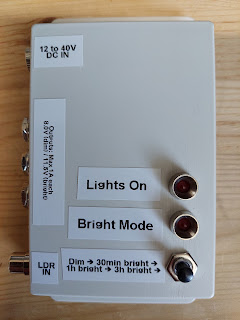
Assembled project
Interior of the project

The case was screwed to the wall and the LDR was positioned where it could be illuminated by light from outside without being illuminated by very much from the lighting it controls, and it works very well.

Saturday, March 20, 2021

Noughts and Crosses Game

First completed: 2011

Introduction

This is a simple electronic game that I made as part of my Art & Design GCSE at school back in 2010/11. The Art & Design GCSE allows creations made from non-traditional materials, and they can even be electronic, as long as they are arty in some way. This project was inspired by Damien Hirst's spot paintings, and uses LEDs to illuminate each of the "spots" a different colour to represent each player.

Pressing the New Game button will start the game. The colour of the player who goes first is random. The game is purely multiplayer and has no AI. Each player takes it in turns to select their spots, and the game ends once the board is full or there are three spots of the same colour in a row.

Construction

The game is constructed on a single-layer board made on the school's simple PCB production facilities - the board was exposed to UV, etched in a tank, and hand-drilled by myself. The front panel is made out of thick card, and the filling is made from foam which has been cut to shape. The buttons are made from stack of different sized cardboard rings which have been glued together so that they can move enough to press the buttons on the PCB but are retained by the front panel. A sheet of tracing paper covers the front and enables the LEDs to produce evenly-coloured spots when lit.

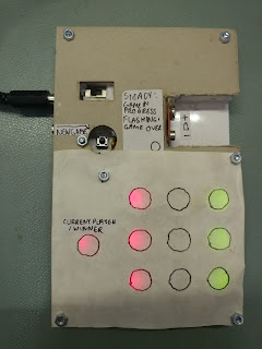
Picture of the Noughts and Crosses Game
Front view of the buttons
Side view of the buttons

Electronics

The game uses a PICAXE-18M2 microcontroller, which is a PIC microcontroller pre-programmed with a BASIC interpreter specifically for the educational market. As a result, it's slow, but it's fine for this application. The 3.5mm jack is used to program the PICAXE microcontroller using a serial cable.

The other DIP ICs on the PCB are serial-to-parallel shift registers which are responsible for driving the LEDs. The only multiplexed part of the design is the matrix keypad. Note that with more programming skill (and probably a faster microcontroller than the PICAXE), the LEDs could have been multiplexed as well, eliminating the need for the external shift registers, but the PICAXE is missing more advanced microcontroller features like timer interrupts (except on larger devices), which would have made multiplexing the LEDs more complex.

A simple 5V linear regulator is used to supply power to the microcontroller from the user's choice of a 9V battery or external DC power supply.

The PCB was originally designed to use 4-pin buttons throughout, but the buttons needed to be substituted with 2-pin buttons so some jumper wires had to be added.

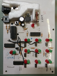
Front view of the PCB
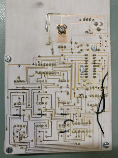
Rear view of the PCB

Tuesday, January 28, 2020

6-inch jumbo radio-controlled LED clock/timer

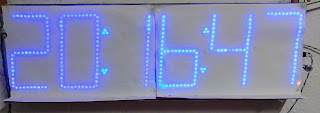
Large radio-controlled 7-segment blue LED clock

First completed: 2013

This was my A2 Level Electronics project, and the objective of this project was to create a clock/timer/stopwatch for a big hall which was large and bright enough to be clearly visible from across the hall. It also needed to synchronise the time automatically, like a radio-controlled clock.

Emphasis was placed on support electronics in my design because it was undesireable for A2 Electronics projects to focus too much on software.

Power supply selection

As good power efficiency over a wide range of operating voltages was desireable, an efficient regulator was required.

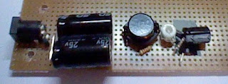
A linear regulator such as the 7805 simply turns "excess" voltage into heat, so if the LEDs required 5V, and the power supply was 20V, the regulator would only be 25% efficient. A switching regulator uses an inductor to efficiently step the voltage down with low losses. The MC34063 switching regulator was selected to ultimately power the LEDs because of its low cost, good availability, and 500mA current rating, which was adequate for the task.

The MC34063 is a rather old switching regulator operating at a low frequency compared to modern ones, but it was fine for this application and it was still a lot more efficient than a linear regulator. The low frequency also meant that the layout of the circuit had little effect on the performance of the switcher.

I tested the efficiency of this regulator with two different supply voltages. Despite the stripboard construction, the efficiency figures were not far off that in the datasheet. 2020 note: Constructing a modern high-frequency switcher this way will totally decimate its performance, based on the author's experience.

Switching regulator efficiency
Switching regulator on stripboard

Microcontroller architecture

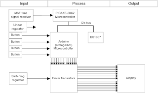
This was one of the author's first Arduino projects and very ambitious for the author's skill level at the time, so the design was simplified a little by delegating the task of decoding the radio-controlled time signal to a PICAXE microcontroller. PICAXE was the first ever microcontroller system used by the author - it is a family of pre-programmed PICs running a special BASIC interpreter and aimed at the educational market; it's too slow to handle all functions of the project, but its key feature of being very easy to configure as an I2C slave made it a perfect fit for the task of handling the radio controlled time decoding. The ATmega328p microcontroller handled almost everything else, except the timekeeping, which was delegated to a DS1307 RTC and backed with a coin cell to allow immediate display of the (roughly) correct time on power-on.

System block diagram

At the time, the author was new to the Arduino/AVR platform, so some of the handy features of the platform, like interrupts, were neglected. The C program runs in a big loop: checking the buttons, performing I2C bus operations, and lighting up each of the six digits one at a time. This was not a real problem though, as the Arduino libraries provided handy functions like millis() to help with timing and there weren't any operations that took a long time to execute.

Radio controlled time (MSF / Time from NPL) signals on oscilloscope

The PICAXE decodes the Time from NPL using the bit-bang method and places it into "scratchpad" (a large block of memory inside the PICAXE that can be read by the I2C Master); the signal was essentially a serial signal with a baud rate of 10. The demodulation from 60kHz was done using a commercial off-the-shelf receiver.

Hardware development

The first prototype was built on breadboard using small 7-segment displays along with an additional microcontroller programmed to simulate the output signal from the radio controlled time receiver; the signal is susceptible to noise, making development using the real receiver difficult.

Prototype of the radio-controlled clock built on breadboard

The circuit was then built up on stripboard to make it permanent along with the addition of the transistors required to drive the big displays, which would be added later. A brightness selector switch was implemented by switching a second trimpot in parallel with the switching regulator's feedback resistor. This board was initially tested with small displays.

Control electronics built on stripboard undergoing testing

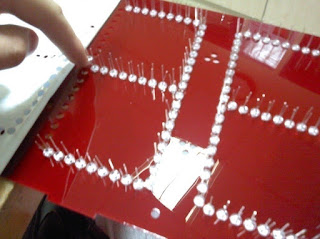
The display was made from a sheet of acrylic cut on the laser cutter. All 408 LEDs were pushed in and soldered by hand.

LEDs being pushed into the sheet of acrylic

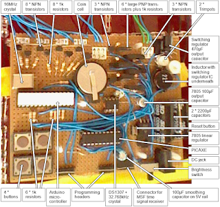
The stripboard assembly was attached to the back of the display.

Picture of the stripboard assembly mounted on the back of the display with all major parts labelled

Summary

The project met its design goals; all intended functionality (clock, stopwatch, countdown timer and radio controlled synchronisation) were implemented and worked, and the display was bright and readable even outside.

Picture of the big clock outside

The power consumption of the display was tested over a wide range of supply voltages. The maximum power consumption with all segments on was 4W.

The code is available on GitHub. The code is extensively commented, but as one of my first Arduino projects, it's far from a shining example of C programming.

Another dimmable LED controller - hacking a switch mode mains power supply

In this blog post, I modified a cheap buck converter module to add a brightness control, and used it to drive a relatively low power strip ...