First completed: 2013
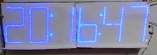
This was my A2 Level Electronics project, and the objective of this project was to create a clock/timer/stopwatch for a big hall which was large and bright enough to be clearly visible from across the hall. It also needed to synchronise the time automatically, like a radio-controlled clock.
Emphasis was placed on support electronics in my design because it was undesireable for A2 Electronics projects to focus too much on software.
Power supply selection
As good power efficiency over a wide range of operating voltages was desireable, an efficient regulator was required.
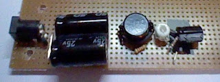
A linear regulator such as the 7805 simply turns "excess" voltage into heat, so if the LEDs required 5V, and the power supply was 20V, the regulator would only be 25% efficient. A switching regulator uses an inductor to efficiently step the voltage down with low losses. The MC34063 switching regulator was selected to ultimately power the LEDs because of its low cost, good availability, and 500mA current rating, which was adequate for the task.
The MC34063 is a rather old switching regulator operating at a low frequency compared to modern ones, but it was fine for this application and it was still a lot more efficient than a linear regulator. The low frequency also meant that the layout of the circuit had little effect on the performance of the switcher.
I tested the efficiency of this regulator with two different supply voltages. Despite the stripboard construction, the efficiency figures were not far off that in the datasheet. 2020 note: Constructing a modern high-frequency switcher this way will totally decimate its performance, based on the author's experience.
Microcontroller architecture
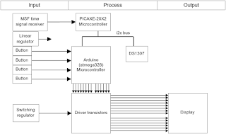
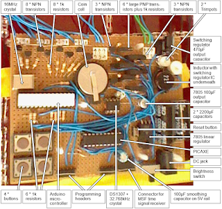
This was one of the author's first Arduino projects and very ambitious for the author's skill level at the time, so the design was simplified a little by delegating the task of decoding the radio-controlled time signal to a PICAXE microcontroller. PICAXE was the first ever microcontroller system used by the author - it is a family of pre-programmed PICs running a special BASIC interpreter and aimed at the educational market; it's too slow to handle all functions of the project, but its key feature of being very easy to configure as an I2C slave made it a perfect fit for the task of handling the radio controlled time decoding. The ATmega328p microcontroller handled almost everything else, except the timekeeping, which was delegated to a DS1307 RTC and backed with a coin cell to allow immediate display of the (roughly) correct time on power-on.
At the time, the author was new to the Arduino/AVR platform, so some of the handy features of the platform, like interrupts, were neglected. The C program runs in a big loop: checking the buttons, performing I2C bus operations, and lighting up each of the six digits one at a time. This was not a real problem though, as the Arduino libraries provided handy functions like millis() to help with timing and there weren't any operations that took a long time to execute.
The PICAXE decodes the Time from NPL using the bit-bang method and places it into "scratchpad" (a large block of memory inside the PICAXE that can be read by the I2C Master); the signal was essentially a serial signal with a baud rate of 10. The demodulation from 60kHz was done using a commercial off-the-shelf receiver.
Hardware development
The first prototype was built on breadboard using small 7-segment displays along with an additional microcontroller programmed to simulate the output signal from the radio controlled time receiver; the signal is susceptible to noise, making development using the real receiver difficult.
The circuit was then built up on stripboard to make it permanent along with the addition of the transistors required to drive the big displays, which would be added later. A brightness selector switch was implemented by switching a second trimpot in parallel with the switching regulator's feedback resistor. This board was initially tested with small displays.
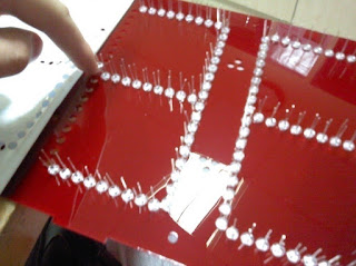
The display was made from a sheet of acrylic cut on the laser cutter. All 408 LEDs were pushed in and soldered by hand.
The stripboard assembly was attached to the back of the display.
Summary
The project met its design goals; all intended functionality (clock, stopwatch, countdown timer and radio controlled synchronisation) were implemented and worked, and the display was bright and readable even outside.
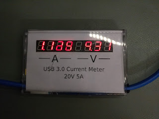
The power consumption of the display was tested over a wide range of supply voltages. The maximum power consumption with all segments on was 4W.
The code is available on GitHub. The code is extensively commented, but as one of my first Arduino projects, it's far from a shining example of C programming.
