I was scavenging two old Sky boxes for parts, and although the very large scale integration of the mid-noughties set-top boxes meant there was very little worth removing, I did extract two of these RF modulators.
RF Modulators convert composite video and audio into an analogue TV channel that can be received on any television set and combines it with the signal from the RF input, enabling the picture from the Sky box to be received on every TV set in the house in addition to the off-air channels. Sky RF modulators are unique in that they have two outputs, one of which features line power and a low-frequency return path to support the "digilink" system, which allows the Sky box to be controlled from the other TVs. See diagram of this setup. This blog entry, however, will focus on the RF output rather than those additional features.


The modulator is completely shielded, but the shielding clips off easily to expose the insides. Much like the rest of the Sky box, the modulator is very highly integrated, and it uses a Freescale MC44BS373CA single chip solution. Impressively for a design which handles signals of up to nearly 1GHz, the modulator is built on a single-layer PCB, presumably to keep costs low. The circuit appears to be largely based on the application circuit in the datasheet, with the addition of some passives and transistors to handle the line power injection, IR return path, and amplification of the RF input. The 75-ohm termination resistor on the video input is missing.
The MC44BS373CA is frequency-agile, which means it can be programmed to work at different frequencies, all the way down to 45MHz in fact. Despite this, the Sky box only allows selection of UHF channels, despite VHF System I still being used in Ireland, so let's find out why not...
Programming the modulator
The modulator has a very simple I2C interface documented in Table 8 in the datasheet, and it supports 5V and 3.3V operation, allowing easy interfacing to Arduino, Raspberry Pi, etc.
The controller is supposed to have a programmable I2C address, but this feature is not available on the package used in this modulator, so it is fixed to 0xCA (8-bit).
There's not a lot of settings that can be configured. The main settings of interest are the oscillator frequency (N11:N0), divider (X2:X0), and test pattern enable (TPEN). The sound frequency bits (SFD1:SFD0) should simply be set to the appropriate setting for the region (10 for System I).
The relationship between frequency, divider and N11:N0 is simple, and I've put it into a table here:
| X2:X0 (Divider) | N11:N0 | F (MHz) |
|---|---|---|
| 000 (1) | 4F | N/4 |
| 001 (2) | 8F | N/8 |
| 010 (4) | 16F | N/16 |
| 011 (8) | 32F | N/32 |
The oscillator is rated for 460MHz to 880MHz, so it's necessary to use the divider to use lower frequencies.
Example project
I made an Arduino sketch to control the modulator. It allows selection of the channel number, from which the frequency and divider are automatically calculated, plus selection of the system (B, D, I, M) and the test pattern.

I haven't included a schematic because the wiring is very simple; all pins are defined in the code. The only important components to remember are the pull-ups on the I2C bus (hidden under the LCD) and the 75-ohm termination resistor between Video In and GND. Failure to include the latter results in horrendous close-spaced ghosting caused by signal reflection.
This controller was used to enable easy control of the modulator during testing.
Real-world testing
My current oscilloscope can only show the spectrun of signals up to 25MHz, so we can't look at the output spectrum, but what we can do is examine the output picture under various different test conditions.
The datasheet gives two figures for the minimum frequency in different places: 30MHz and 45MHz. The latter seemed to be true.
The programmable oscillator seemed to work down to about 400MHz, below which there was no output and it was necessary to up the divider. It worked fine up to 900MHz, the highest any TV I had went up to, so it may have gone even higher.
The single-sided board didn't seem to compromise the quality at higher frequencies.
The picture had lots of 'sparklies' when using the highest divider (16). It's not needed to access the lowest frequencies anyway.
Harmonics
What parts are of particular interest? These graphs...
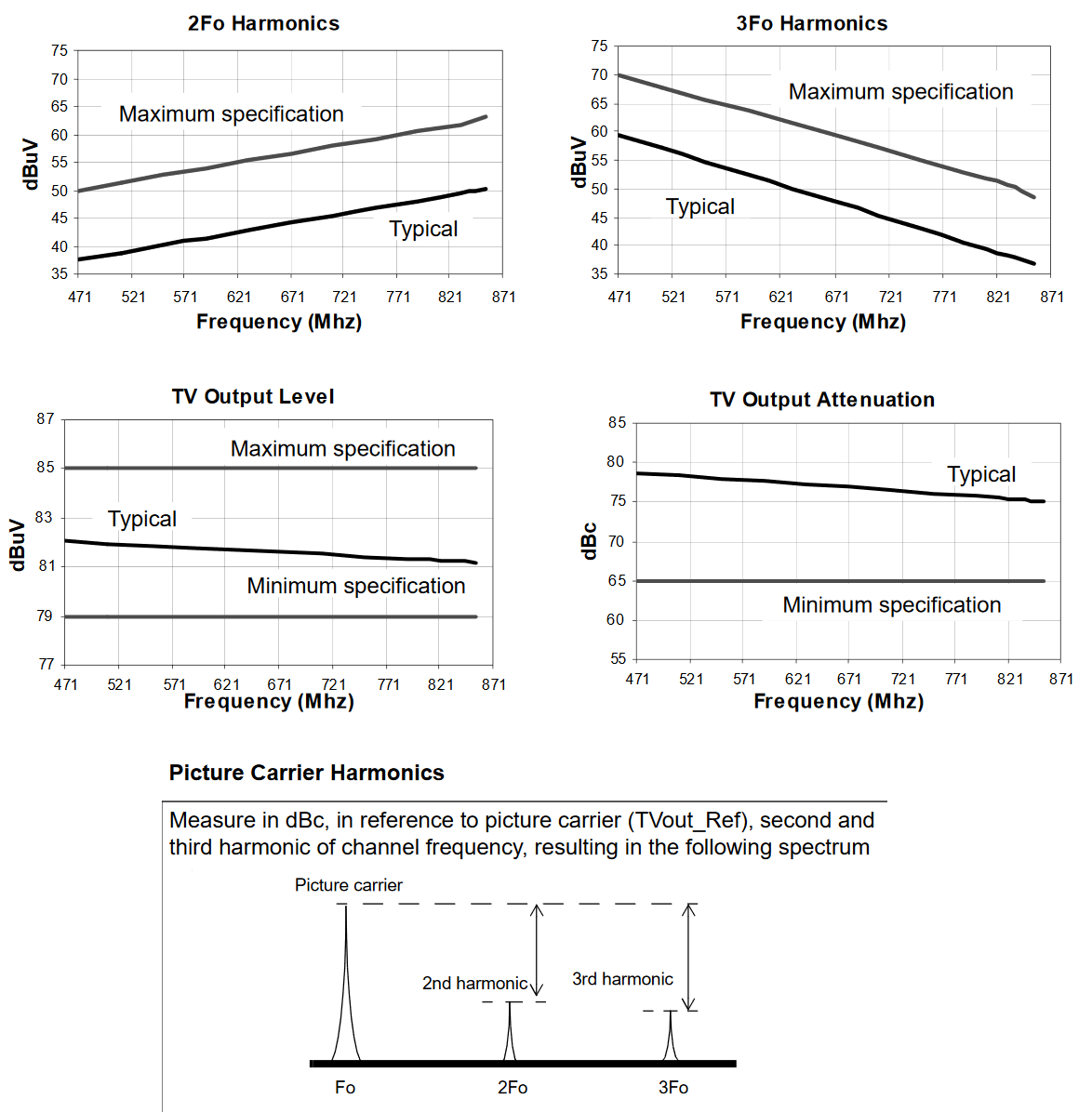
Look at the signal levels of those harmonics. Unlike this newfangled digital stuff, analogue TV is very suspectible to interference, and a signal to noise ratio of 46dB is required for noise-free viewing. These harmonics result in a signal to noise ratio well below that at affected frequencies, which will spoil anything on those frequencies. The 2nd harmonic is at two times the set frequency, 3rd at three times, and so on, so this isn't a problem when using UHF output frequencies, but at VHF output frequencies, this becomes a problem.
Example 1: Set frequency (1st harmonic) 119MHz, harmonics at 357MHz, 595MHz, 833MHz.
Example 2: Set frequency (1st harmonic) 48MHz, harmonics at 144MHz, 240MHz, 336MHz, 432MHz, 528MHz, 624MHz, 720MHz, 816MHz.
Here we examine the harmonics on a TV screen when the test pattern is enabled. The datasheet only shows graphs for the 2nd and 3rd harmonics, but in fact there's a lot more where those came from; whilst I couldn't find the 4th harmonic, the 5th, 7th, 9th, and so on, are quite strong too, but each harmonic is weaker than the last.
Now let's see what happens when one of those harmonics happens to correspond to a TV channel. An analogue channel is viewed on C24 (495.25MHz), and the modulator is set to 165.08MHz (then 99.05MHz) so that the third harmonic (fifth harmonic) is at the same frequency as the channel being viewed. Note that the Arduino example cannot select this frequency, so a direct I2C write is required (N=2641, divider=4).
Unsurprisingly, the result is terrible co-channel interference, which looks like this:

When the third harmonic is the source of the interference, it is possible to see a faint image of the picture being transmitted by the programmable modulator. The interference is reduced with higher harmonics. The last screenshot shows the quality of the 5th harmonic with the source of the real C24 disconnected.
Noise of a different kind
The convenient 5V power supply makes it tempting to power projects using it from a phone charger. This should be done with great care, as any noise from the power supply will be visible on the modulated output. I can't provide a screenshot of this; the picture has to be watched to understand the irritation of the effect properly.
Summary
These modulators provide good results and flexibility as long as their limitations are considered. The I2C interface allows easy programming and integration into video-based microcontroller projects such as VBIT-Pi (as long as the noise is considered), and the loopthrough and dual outputs allow easy integration into TV distribution systems. The only real limitation is that when VHF channels are used, it will usually be necessary to use external output filters to combine the new channel with a distributon system to avoid interference from the harmonics.
Other bonuses of this modulator include the high signal output level, which allows the signal to be split to many TVs without introducing noise, plus I believe the RF input is amplified a bit too, though I haven't been able to test that.


