First completed: 2011
Introduction
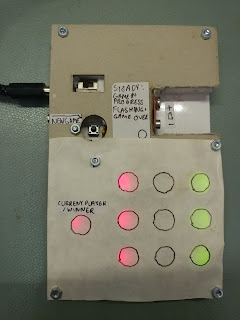
This is a simple electronic game that I made as part of my Art & Design GCSE at school back in 2010/11. The Art & Design GCSE allows creations made from non-traditional materials, and they can even be electronic, as long as they are arty in some way. This project was inspired by Damien Hirst's spot paintings, and uses LEDs to illuminate each of the "spots" a different colour to represent each player.
Pressing the New Game button will start the game. The colour of the player who goes first is random. The game is purely multiplayer and has no AI. Each player takes it in turns to select their spots, and the game ends once the board is full or there are three spots of the same colour in a row.
Construction
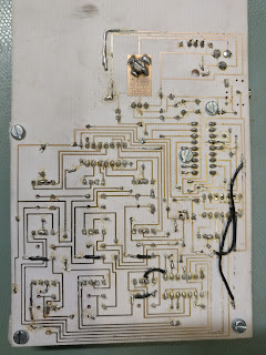
The game is constructed on a single-layer board made on the school's simple PCB production facilities - the board was exposed to UV, etched in a tank, and hand-drilled by myself. The front panel is made out of thick card, and the filling is made from foam which has been cut to shape. The buttons are made from stack of different sized cardboard rings which have been glued together so that they can move enough to press the buttons on the PCB but are retained by the front panel. A sheet of tracing paper covers the front and enables the LEDs to produce evenly-coloured spots when lit.
Electronics
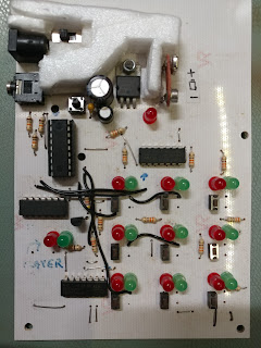
The game uses a PICAXE-18M2 microcontroller, which is a PIC microcontroller pre-programmed with a BASIC interpreter specifically for the educational market. As a result, it's slow, but it's fine for this application. The 3.5mm jack is used to program the PICAXE microcontroller using a serial cable.
The other DIP ICs on the PCB are serial-to-parallel shift registers which are responsible for driving the LEDs. The only multiplexed part of the design is the matrix keypad. Note that with more programming skill (and probably a faster microcontroller than the PICAXE), the LEDs could have been multiplexed as well, eliminating the need for the external shift registers, but the PICAXE is missing more advanced microcontroller features like timer interrupts (except on larger devices), which would have made multiplexing the LEDs more complex.
A simple 5V linear regulator is used to supply power to the microcontroller from the user's choice of a 9V battery or external DC power supply.
The PCB was originally designed to use 4-pin buttons throughout, but the buttons needed to be substituted with 2-pin buttons so some jumper wires had to be added.


