Introduction
This is a simple project which is a lighting controller for the inexpensive LED tape which is widely available from marketplace sites and is designed to be powered from 12V.
The requirements for this project were:
- Automatically turn the LEDs on at dusk and turn them off at dawn
- Run the LEDs at a dim brightness during normal operation, or at high brightness when high brightness mode is enabled
- Have a button for selecting high brightness mode. High brightness mode shall automatically be turned off after a time period
- Have good efficiency
Preliminary testing
Prior to building the controller, the waterproof LED tape was installed as desired around the outside of my house. Around 8 metres of LED tape was installed in three separate lengths and mains flex was wired between each of the three runs and a central location where the controller will be installed along with its light sensor.
The LED tapes were all connected to a bench power supply in parallel for testing.
At the design voltage of 12V, the LEDs are at full brightness and consume around 2A of current for a total of 24W of power. The LEDs are quite bright at this power and the brightness is far too excessive to be used all night, not to mention the high operating costs over the long term.
The voltage was turned down until a sensible brightness for all-night operation was found. This was found to be in the range of 7.90V to 8.10V, with the current varying from 0.05A to 0.10A, and the power from 0.395W to 0.810W. With this in mind, a target voltage of 8.00V was chosen, which should result in a power consumption of only 0.6W (plus overheads from the mains power supply), resulting in low running costs.
Design
The power section of the design was be based around one of the inexpensive and widely available LM2576 buck converter boards. The board was modified to replace the trimmer potentiometer with fixed resistors to avoid future unreliability, and the Enable pin was carefully desoldered from the PCB so that it could be externally driven. A connection was also added to the feedback junction so that an extra resistor could be wired in parallel with the main resistor; this would form the basis of the brightness selection, where this resistor can be left floating or shorted to GND via a transistor to modify the lower resistance value in the feedback network and hence change the output voltage of the buck converter.
Originally I planned to use a comparator wired as a schmitt trigger to control the Enable pin and a 555 timer in monostable mode to control the high brightness mode, but I decided to change to a microcontroller to allow more flexibility and make it easy to implement multiple time-out periods for the high brightness mode which can be stepped through by pressing the button repeatedly. I used a PICAXE-08M (educational microcontroller) since I already had a few, but a bare PIC or ATtiny would also work well.
Hardware
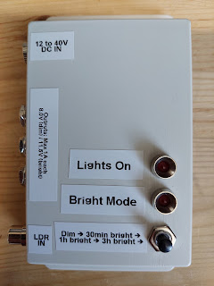
I built most of the circuit on stripboard and placed all the components to allow it to fit inside a plastic case.
Some extra resistors have been used in the feedback network compared to the schematic to trim the output voltage more accurately. Polyfuses were also added to each of the three outputs to provide independent short-circuit protection for each channel, which I thought would be a good idea given that the lights are outside.
The case was screwed to the wall and the LDR was positioned where it could be illuminated by light from outside without being illuminated by very much from the lighting it controls, and it works very well.


No comments:
Post a Comment